
Trying to make sense of a full set of construction plans can feel like you've been handed a book in a foreign language. It's just pages and pages of lines, symbols, and numbers that, at first glance, look completely overwhelming.
But here’s the secret: you just need to know where to start. Don't try to decipher the whole thing at once. Your first stop should always be the cover sheet.
Think of the cover sheet as the project's dashboard. It gives you all the high-level, critical information you need for context. This is where you'll confirm the official project name, the physical address, and see which architectural and engineering firms are on the job. It’s the who, what, and where of the entire build, all in one place.
Find Your Way with the Title Block and Sheet Index
On every single page of the blueprint set, you'll find a title block, usually tucked into the bottom right-hand corner. This small section is packed with vital information specific to that sheet.
You'll find things like:
- Sheet Title: A clear description of what you're looking at, like "First Floor Plan" or "East Elevation."
- Sheet Number: A unique code (e.g., A-101 for an architectural drawing) that acts as a page number, helping you reference it later.
- Drawing Scale: This tells you how the drawing relates to the real world (for example, 1/4" = 1'-0").
- Revision History: A log of any changes made to the drawing, so you can be sure you're working off the latest version.
Working hand-in-hand with the title block is the sheet index, which you'll almost always find on the cover page. This is your table of contents for the entire set of drawings. It lists every single sheet by its number and title, neatly organizing the project into disciplines like Architectural (A), Structural (S), and Electrical (E).
Before you get lost in the details of a specific plan, it's a good habit to spend a few minutes with the sheet index. It gives you a mental map of the whole project—how many pages are dedicated to plumbing, where to find the structural details, and so on. It’s a simple step that saves a ton of time and prevents confusion down the road.
Getting a handle on these documents is a game-changer for any project. For homeowners, this is especially true when you're planning a bathroom renovation and need to understand the design before the first tile is laid. By starting with the title block and sheet index, you build a solid foundation for making sense of all the complex details that follow.
To give you a better idea of what to expect in a full set of plans, here's a quick rundown of the most common sections you'll encounter.
Key Sections of a Blueprint Set
| Sheet Type | Sheet Code Prefix | Information Included |
|---|---|---|
| Cover Sheet | G (General) | Project name, address, sheet index, architectural renderings, key contacts. |
| Civil Drawings | C | Site plans, grading, utility layouts, landscaping, and property lines. |
| Architectural Drawings | A | Floor plans, elevations, building sections, wall details, door/window schedules. |
| Structural Drawings | S | Foundation plans, framing details, beam and column schedules, structural notes. |
| Mechanical Drawings | M | HVAC system layouts, ductwork plans, equipment schedules. |
| Plumbing Drawings | P | Piping diagrams, fixture locations, water supply, and drainage systems. |
| Electrical Drawings | E | Lighting plans, power outlets, circuit diagrams, panel schedules. |
Familiarizing yourself with these prefixes makes navigating a large set of drawings much faster. When you know an "S" sheet is structural, you won't waste time hunting for framing details in the "A" section.
Decoding the Language of Lines and Symbols
Once you get past the title block, you'll find that blueprints tell their story through a unique visual language. It’s a shorthand of lines and symbols, where every thickness, style, and placement has a specific job. Learning this language is what turns a confusing drawing into a clear set of instructions, letting you see the architect's vision exactly as they intended.
The most basic building blocks are the lines themselves. They aren't just random marks; they create a hierarchy of information that guides your eye through the structure. It’s this visual shorthand that allows a simple two-dimensional drawing to represent a complex, three-dimensional building with incredible precision.
The Hierarchy of Lines
Think of the different lines as having different "voices." Some are bold and command your attention, while others are more subtle, offering supporting details. The main ones you’ll run into are:
- Object Lines: These are the heavy hitters—thick, solid lines that show the visible edges of a building or object. When you see the main outline of a wall on a floor plan, that’s an object line.
- Hidden Lines: You'll see these as dashed or dotted lines. They represent important features that you can't see from the current viewpoint, like a foundation footing that sits below the concrete slab.
- Center Lines: These are drawn as long-short-long dashes and are used to mark the exact center of symmetrical items like columns, windows, or doors. They are absolutely critical for getting the placement right during the build.
A rookie mistake is to treat all lines the same. The weight and style are deliberate. A thick object line is far more important than a thin dimension line, and it’s designed to pull your focus to the main structure first.
To get the hang of it, think about reading the plans from the big picture down to the smallest details.
This graphic breaks down the typical workflow for reading blueprint symbols.
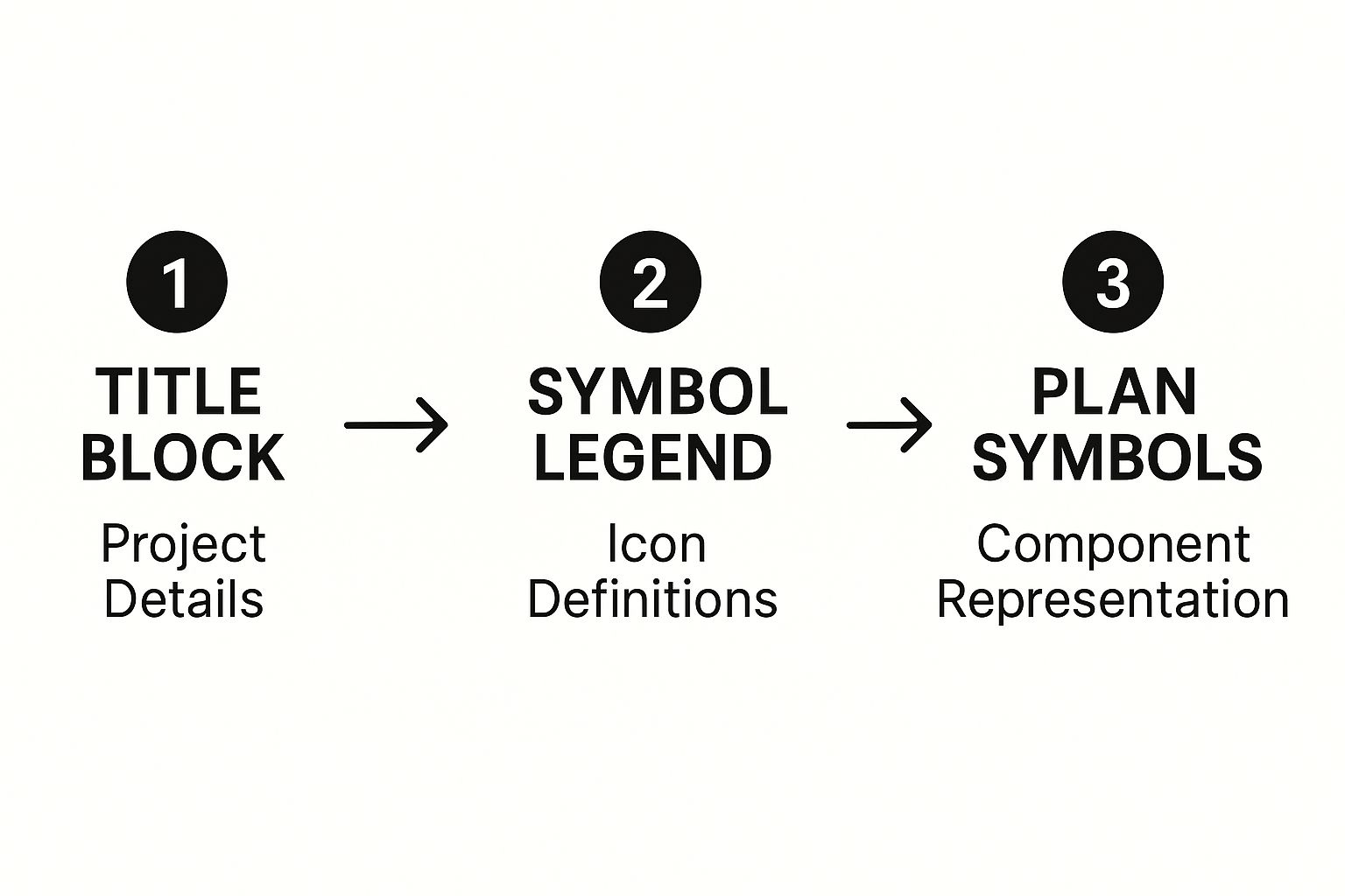
It shows why you should always start with the general project info before diving into the individual symbols scattered across the plans.
From Lines to Symbols
After you’ve got a feel for the lines, the next step is interpreting symbols. These are standardized icons representing everything from a door’s swing to a toilet to an electrical outlet. The key to cracking this code is the drawing legend or symbol schedule, which is almost always located on one of the first few pages of the blueprint set.
For example, a simple circle with two parallel lines usually represents a standard duplex outlet, while a quarter-circle arc shows you which way a door swings open. You’ll find symbols for plumbing fixtures, HVAC vents, and everything in between. While most are standardized, architects sometimes use custom ones, which is why checking the legend on every single project is a non-negotiable habit. For more specialized work, like custom millwork, you'll need to know how to read cabinet blueprints to decipher those detailed drawings.
This skill is the backbone of the entire global construction market, which hit a value of roughly $11.39 trillion in 2024. As this industry keeps growing, correctly reading these documents remains an essential skill for getting projects done right anywhere in the world. By mastering this visual language, you're tapping into a universal system that turns lines on a page into the places we live and work.
Mastering Scale and Reading Dimensions
Blueprints are pretty amazing when you think about it. They take a massive, real-world building and shrink it down onto a sheet of paper you can actually work with. This magic is possible because of scale—a precise ratio that tells you how measurements on the drawing translate to actual size on the job site. Getting this right isn't just a small detail; it’s the foundation of the entire build.
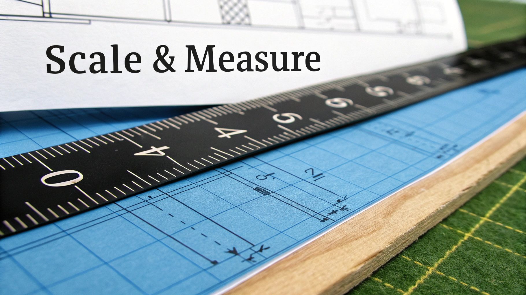
You'll almost always find the scale listed in the title block of each sheet. For most residential and commercial projects, you're going to see 1/4" = 1'-0" more often than not. This is simple: every quarter-inch you measure on the paper equals one full foot in the real world.
To measure it properly, you’ll need an architect's scale. It’s that triangular ruler with a bunch of different scales on each edge. Just find the side marked "1/4," line up its zero mark with the start of a wall, and read the number where the wall ends. It’s a direct translation, which means no fumbling with a calculator on site.
From Scale to Specifics
Once you've got a feel for the overall scale, your eyes will naturally drift to the dimension strings. These are the lines with numbers you see running alongside walls and other features on a floor plan. They give you the exact measurements needed to build, leaving zero room for guesswork.
Dimension strings are usually layered for clarity:
- Innermost String: This is where you find the nitty-gritty details, like the widths of doors and windows and the spacing between them.
- Middle String: This one often marks the centerlines for key features, which is critical for getting placement just right.
- Outermost String: This gives you the overall length of a wall or a whole section of the building. It's your big-picture measurement.
Pro Tip: Always, always trust the numbers written on the dimension strings, not what you measure with your scale. A drawing can have tiny printing inaccuracies, but those printed dimensions are the legally binding measurements the architect specified.
Putting Dimensions into Practice
Let's say you're framing a wall that has a window in it. The dimension string will tell you the exact distance from the corner of the room to the edge of the window's rough opening, the width of that opening, and then the distance to whatever comes next. This level of detail is what prevents costly mistakes, like framing a window six inches off from where it should be—a simple error that can throw off electrical wiring, exterior siding, and a whole lot more.
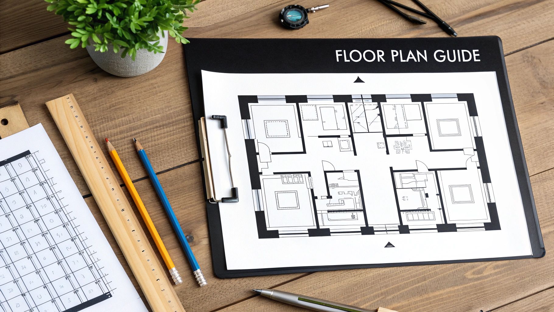
As you get better at this, you'll see how critical a solid grasp of the floor plan is. If you're looking to go deeper, understanding floor plans is the next logical step to really build up your expertise.
The same principles apply to everything else, even the really detailed stuff like cabinetry. In fact, getting these basics down is perfect prep work if you're planning a renovation and need to follow an expert guide to measure kitchen cabinets. The logic is exactly the same: start with the big-picture scale, then rely on the specific dimensions to get the job done right. Mastering this skill is what turns a page of abstract lines into a clear, actionable roadmap for a successful project.
Connecting Different Blueprint Views and Elevations
A building is a three-dimensional object, but blueprints are flat, two-dimensional drawings. The real skill in learning how to read construction blueprints is training your brain to assemble these flat views into a complete 3D picture in your mind. This is where you learn to see how the top-down plan connects to the side views and even the internal structure.
This process involves understanding the three primary types of drawings that work together to tell the full story of the building. Each one offers a unique perspective, and mastering how they relate to one another is crucial for avoiding on-site confusion. Think of it as looking at a model house from the top, the sides, and then slicing it in half to see inside.
You’ll find yourself constantly flipping between three core views:
- Floor Plans: This is the one everyone knows—a bird's-eye view of the layout as if you sliced the roof off. It shows you room dimensions, where the walls go, and the placement of doors and windows.
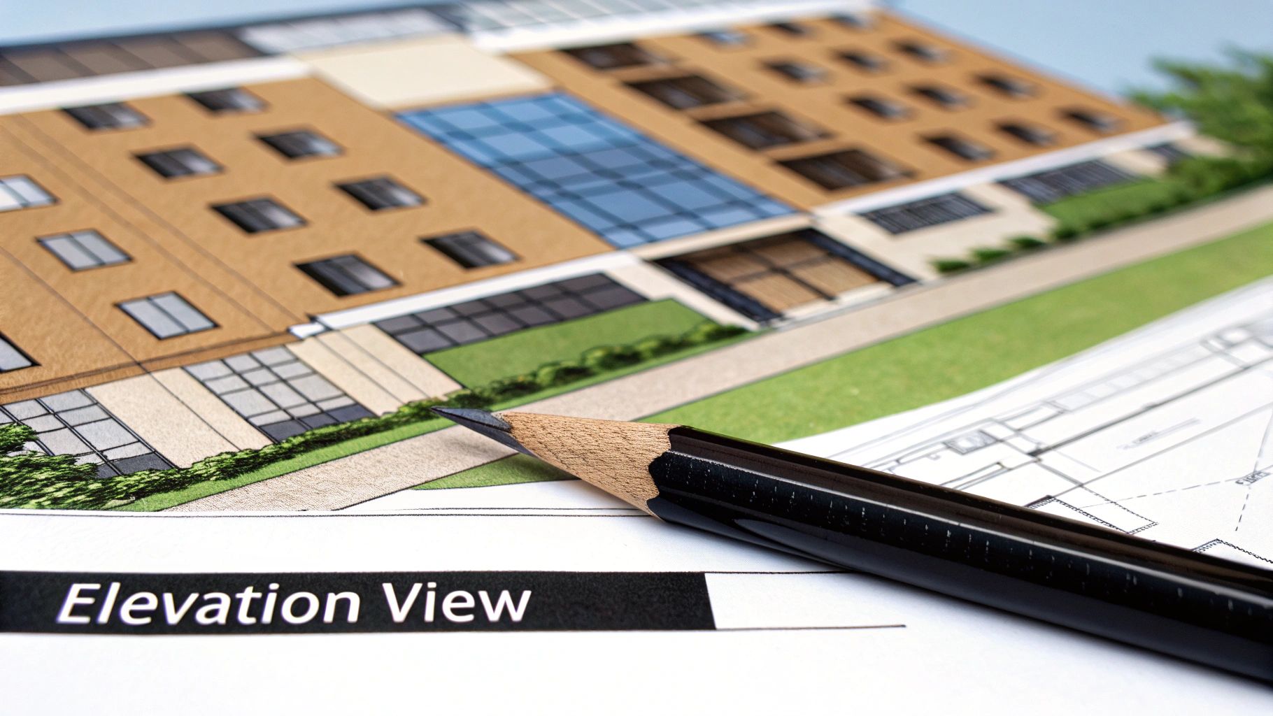
- Elevations: These drawings show what the building’s exterior looks like from one side. You'll have a separate elevation for the front, rear, and each side, illustrating the exterior finishes, window styles, and roof heights.
- Sections: A section view is like a slice right through a part of the building, revealing its guts. It’s how you see the construction of a wall, the foundation details, or how a roof is framed.
Following the Trail of Callout Symbols
So, how do all these different views connect? The magic is in the callout symbol. Architects use these little markers to guide you from a general drawing to a more detailed one on another page. A callout is your roadmap, making sure no critical detail gets lost.
For instance, you might see a circle with a number and letter inside it on the floor plan, pointing to a specific wall. That symbol is essentially saying, "Hey, for a detailed, slice-through view of this wall's construction, go to drawing A-501, detail #3." Following that reference is how you confirm things like insulation type, stud spacing, and interior finishes.
A rookie mistake is to only look at the floor plan and assume you have the full story. The real details that prevent costly errors are almost always tucked away in the section or detail drawings, and callout symbols are the only way to find them.
A Practical Example From Plan to Reality
Let’s trace a common feature to see how this works in the real world. Imagine you're looking at a floor plan and you see a staircase. The floor plan will show its location and general shape, but that's about it. It won't tell you how to actually build it.
Somewhere nearby, you’ll find a callout symbol. This symbol directs you to a separate section view of that staircase on another sheet. On that new drawing, you’ll find all the mission-critical details:
| Detail | Description |
|---|---|
| Rise & Run | The precise height of each step and the depth of each tread. |
| Stringer Info | The material and size of the structural supports for the stairs. |
| Headroom | The vertical clearance to ensure the staircase is safe and up to code. |
| Material Specs | Notes specifying the type of wood for treads and handrails. |
By following that simple callout, you've moved from a basic layout to a detailed construction guide. This cross-referencing skill is what truly separates someone who can just look at blueprints from someone who can read and understand them. It’s how you ensure every component, from the foundation to the roof, fits together exactly as the architect intended.
Finding Critical Details In Schedules and Notes
The lines and symbols on a set of blueprints only tell part of the story. To really get a handle on a project's full scope, you have to dig into the text—the general notes, the schedules, and the specifications. This is where architects lay out all the critical information that can't be squeezed into a drawing, turning a simple floor plan into a detailed construction manual.
Think of it this way: the floor plan shows you where a window goes, but the window schedule tells you exactly what kind of window it is. Schedules are just tables that neatly organize complex information for specific building components like doors, windows, lighting fixtures, and finishes.
What Are Schedules?
Schedules are your go-to reference for getting the details right. A door schedule, for example, will list every single door by a number or code and then break down everything you need to know about it.
- Dimensions: The precise width, height, and thickness.
- Material: Is it solid core wood, hollow core, or steel?
- Hardware: Details on the hinges, doorknobs, locksets, and closers.
- Fire Rating: Any required fire-resistance rating—absolutely crucial for safety and code compliance.
Ignoring these schedules is a classic (and costly) mistake. I’ve seen projects get held up for weeks because someone ordered the wrong size windows or incorrect door hardware. Those kinds of errors lead to major delays and budget blowouts.
Don't Skip the General Notes
Before you even glance at a floor plan, make it a habit to read the general notes. This section, usually found on one of the first few sheets of the drawing set, contains the project-wide rules that apply to the entire build. It’s where you'll find information about building codes, standards for material quality, and general construction practices the architect expects everyone to follow.
Think of the general notes as the project's rulebook. They often clarify what to do if information seems to conflict between different drawings, establishing a clear hierarchy of documents. In short, they are the architect’s direct instructions.
This text is just as legally binding as the drawings themselves. For homeowners planning a renovation, this is where you'll find specifics on everything from the required drywall thickness to the type of paint finish for each room. These details often connect to other specialized areas, like the millwork section, which might reference specific cabinet construction details.
Tying It All Together With Schedules
To make this easier, let's look at the most common schedules you'll encounter on a set of plans. Each one is designed to give you a quick, organized summary of essential components so you don't have to hunt through pages of notes to find what you're looking for.
Common Blueprint Schedules and Their Purpose
| Schedule Type | What It Specifies | Example Information |
|---|---|---|
| Door Schedule | Every detail about every door in the project. | Door #101: 3'-0" x 6'-8", Solid Core Wood, Satin Nickel Lever, 90-Min Fire Rating |
| Window Schedule | Type, size, material, and glazing for all windows. | Window A: 36"x48" Double-Hung, Vinyl, Low-E Glass, Argon Filled |
| Finish Schedule | Room-by-room breakdown of all surface materials. | Living Room: Floor – Oak Hardwood; Walls – "Agreeable Gray" Eggshell Paint; Ceiling – Flat White |
| Lighting Schedule | Fixture types, locations, lamping, and controls. | Kitchen: (4) 6" LED Recessed Cans, 3000K; (1) Pendant over Island, Model XYZ |
| Plumbing Schedule | Specific models for all fixtures and fittings. | Master Bath: Sink – Kohler K-2240; Faucet – Delta Trinsic; Toilet – Toto Drake II |
By taking the time to cross-reference these schedules with the drawings, you ensure that every material, fixture, and finish aligns perfectly with the architect’s vision. It’s the best way to prevent rework and guarantee a high-quality result.
Common Questions About Reading Blueprints
Even after you've got the basics down—scales, symbols, and views—practical questions always pop up on the job site. Knowing how to troubleshoot common issues is a huge part of really learning how to read construction blueprints, not just look at them. This is where the rubber meets the road.
Getting handed a new set of plans can feel a little overwhelming, but a systematic approach makes all the difference. If you know where to start, you won't get lost in the details too early.
What's the First Thing to Look At?
Always start with the cover sheet and the sheet index. The cover sheet is your project's ID card—it has the address, the architect's details, and other high-level info. Right after that, flip to the sheet index. Think of it as your table of contents; it tells you exactly what drawings are in the set (like A-1 for the first architectural sheet, S-1 for structural, and so on).
From there, find the general notes and the symbol legend. These sections are your cheat sheets. They define the project-wide rules and explain what all those little icons mean, giving you a solid foundation before you ever look at a floor plan.
What Should I Do If I Find Conflicting Information?
It happens more often than you'd think. You might see an architectural plan showing a wall in one spot and a structural plan showing it just a few inches off. It's a classic job site headache. A good rule of thumb is that more specific information, like a detailed callout or section view, usually overrides a general floor plan.
But here’s the most important part: never assume. Don't just pick one and run with it. The only correct way to handle this is to submit a Request for Information (RFI) to the project manager or architect. This creates a formal paper trail, gets everyone on the same page with the right information, and most importantly, protects you from being liable for a costly mistake.
This formal step isn't just bureaucracy; it's what keeps a project from going off the rails and prevents expensive rework down the line.
What's the Difference Between Blueprints and As-Builts?
This is a critical distinction, and mixing them up can cause major confusion. They look similar but serve completely different purposes at different stages of a project.
- Construction Blueprints: These drawings show what is intended to be built. They are the forward-looking plan created by the design team before a single shovel hits the ground.
- As-Built Drawings: These are created after construction is finished. The contractor marks up the original blueprints to reflect any changes, modifications, or deviations made during the building process. They show the final, actual state of the project.
Think of it this way: the blueprint is the recipe, while the as-built shows you exactly what came out of the oven, including any substitutions the chef made along the way. As-builts are incredibly valuable for future maintenance or renovations because they show the true locations of hidden pipes, wiring, and structural elements—not just where they were supposed to be.
At Sinclair Cabinetry inc, we bring over 35 years of expertise to every detail, ensuring your vision is built with precision from the initial plans to the final installation. Explore our custom cabinetry solutions to see how we turn blueprints into beautiful realities.